Finite State Machines (FSMs) are models used to represent processes where only one state can exist at a time. From a few of my previous tutorials, you'll already have the theory — in this one we get hands-on and model a washing machine cycle using VHDL.
We'll use Digital as our simulation environment throughout, and lean on Brock J. LaMeres' book — Introduction to Logic Circuits & Logic Design with VHDL as a reference. Let's go.
1. Word Description
Before touching any code or diagram, a clear word description is essential. It defines the behaviour of the machine precisely enough that everything that follows — state diagrams, logic, simulation — can be derived directly from it.
The design of the washing machine begins in an idle state, waiting for the presence of clothes (C), detergent (D), and water (W). Once all are available, it transitions to the fill_water state to prepare for washing. The machine then moves through wash, drain, rinse, and spin states sequentially, simulating each stage of the washing process. In each state, the appropriate outputs — L for clothes load, and U for used water — are set based on the current state. The cycle completes in the done state, where the machine returns to idle, ready for the next load.
From this description we can extract everything we need: inputs C, D, W; outputs L and U; and seven distinct states.
| State | Transitions to | L | U |
|---|---|---|---|
| idle | fill_water (if C=D=W=1), else stays idle | 0 | 0 |
| fill_water | wash | 0 | 0 |
| wash | drain | 0 | 0 |
| drain | rinse | 1 | 1 |
| rinse | spin | 1 | 1 |
| spin | done | 1 | 0 |
| done | idle | 1 | 0 |
2. Drawing a State Diagram
A state diagram is a visual representation of the whole machine — every state, every transition, and where inputs and outputs live in the picture. It's the single most useful reference document for the implementation that follows.
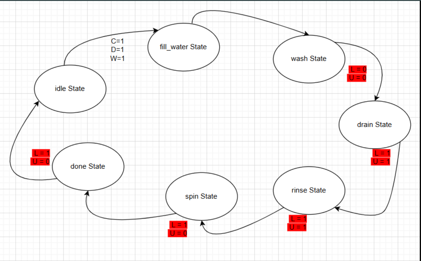
Figure 1: FSM state diagram — outputs in red, inputs in black
Colour convention
Outputs are marked in red on the diagram; inputs are in black. This makes it immediately clear what the machine reads versus what it drives.
3. Synthesis of the FSM
Every state machine in hardware decomposes into three distinct blocks. Understanding each one before writing code makes the VHDL structure feel natural rather than arbitrary.
| Block | Function | Logic type |
|---|---|---|
| State Memory | Holds the current state; updates on clock edge | Sequential |
| Next State Logic | Computes next state from current state + inputs | Combinational |
| Output Logic | Derives outputs from current state | Combinational |
a. State Memory
The state register is clocked. On a rising edge of Clk it moves to next_state; an active-low Reset forces it back to idle asynchronously — indicated by the ">" symbol on the block diagram.
State_Memory : process (Reset, Clk) is
begin
  if (Reset = '0') then
    current_state <= idle;
  elsif rising_edge(Clk) then
    current_state <= next_state;
  end if;
end process;
b. Next State Logic
This is a purely combinational process sensitive to current_state and all three inputs. A case statement evaluates every state and selects the appropriate transition. Only idle branches on inputs — all other states advance unconditionally.
Next_State_Logic : process (current_state, C, D, W) is
begin
  case current_state is
    when idle =>
      if (C = '1' and D = '1' and W = '1') then
        next_state <= fill_water;
      else
        next_state <= idle;
      end if;
    when fill_water => next_state <= wash;
    when wash       => next_state <= drain;
    when drain      => next_state <= rinse;
    when rinse      => next_state <= spin;
    when spin       => next_state <= done;
    when done       => next_state <= idle;
    when others     => next_state <= idle;
  end case;
end process;
c. Output Logic
The output logic creates the system outputs. Because the sensitivity list contains only current_state, this is a Moore machine — outputs depend solely on state, not on inputs directly. Default assignments at the top of the process keep the logic safe against unhandled states.
Output_Logic : process (current_state) is
begin
  L <= '0';
  U <= '0';
  case current_state is
    when wash          => L <= '0'; U <= '0';
    when drain | rinse => L <= '1'; U <= '1';
    when spin  | done  => L <= '1'; U <= '0';
    when others        => L <= '0'; U <= '0';
  end case;
end process;
Default assignments matter
Setting L <= '0' and U <= '0' before the case statement prevents unintended latches. Without defaults, any state not explicitly listed could infer storage — a common synthesis gotcha.
4. Simulation
With the three processes assembled into a complete entity, open Digital. Paste the full VHDL into the component field and verify no errors appear.
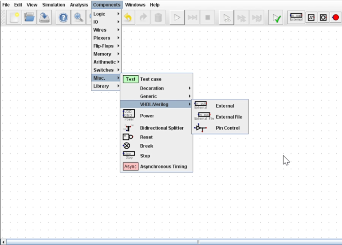
Figure 2: The Digital simulation tool
Next, wire up the schematic: add a clock, a reset line, the three condition inputs C, D, W, and two LED outputs for L and U.
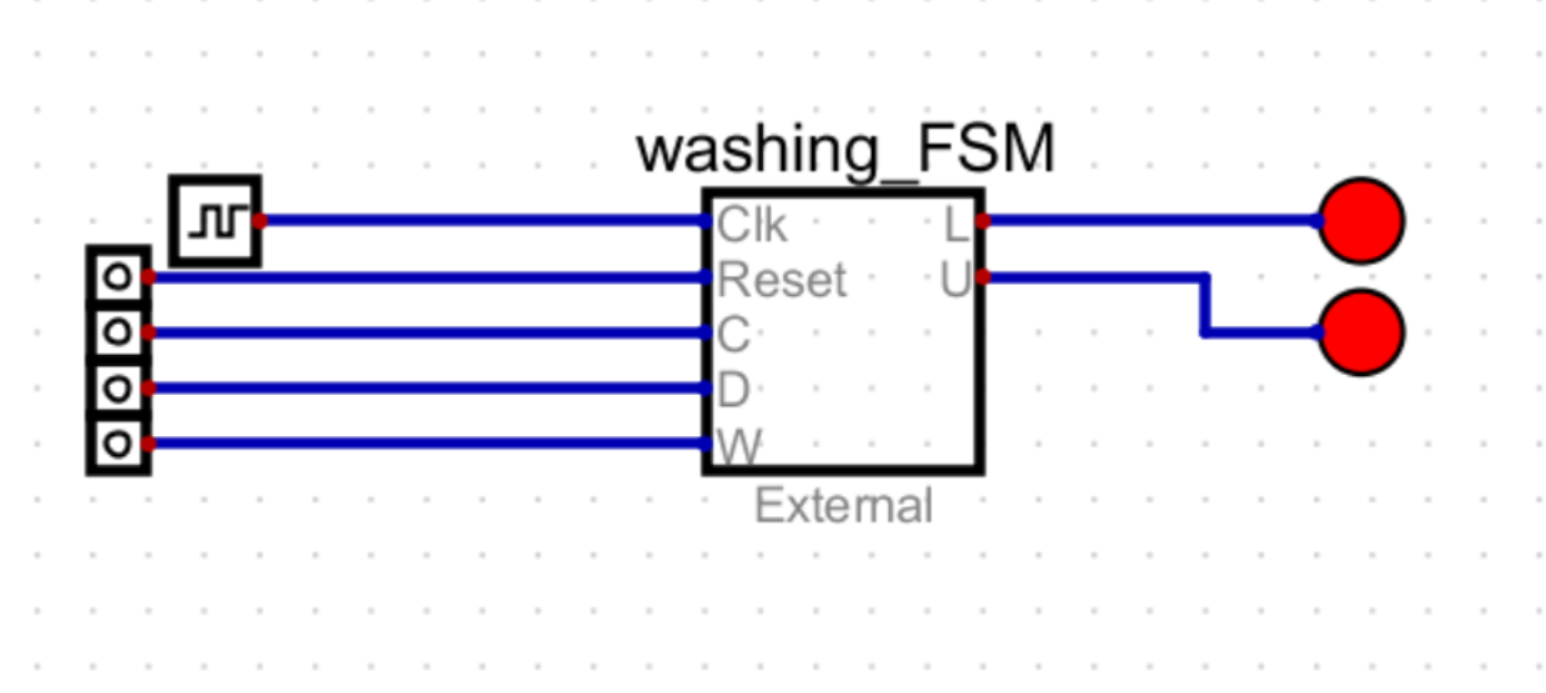
Figure 3: Wired schematic - clock, reset, C/D/W inputs, and LED outputs
Run the simulation and step through clock cycles. The LEDs should track the output table exactly: dark through idle → fill_water → wash, both lit through drain → rinse, only L lit through spin → done, then back to idle.
Check Reset polarity
The Reset signal is active-low in this design — the machine is held in idle when Reset = '0'. Tie Reset high during normal operation, or the FSM will never leave idle regardless of C, D, W.
5. Full VHDL Listing
The complete entity and architecture for reference. Copy this directly into Digital's component field.